Camera Models
Forward Projection (3D → 2D)
The complete pipeline from a 3D world point to a 2D pixel:

World Space → [R|t] → Camera Space → [÷ Z_c] → Image Plane (z=1) → [distort] → Distorted Space → [K] → Pixel Space
(X, Y, Z)            (X_c,Y_c,Z_c)              (x_n, y_n)                       (x_d, y_d)              (x, y)
Step 1: World Space → Camera Space
Transform the 3D world point (X, Y, Z) into the camera coordinate frame using the extrinsic matrix [R | t]:
⎡ X_c ⎤       ⎡ r₁₁  r₁₂  r₁₃ ⎤   ⎡ X ⎤     ⎡ t_x ⎤
⎢ Y_c ⎥   =   ⎢ r₂₁  r₂₂  r₂₃ ⎥   ⎢ Y ⎥  +  ⎢ t_y ⎥
⎣ Z_c ⎦       ⎣ r₃₁  r₃₂  r₃₃ ⎦   ⎣ Z ⎦     ⎣ t_z ⎦
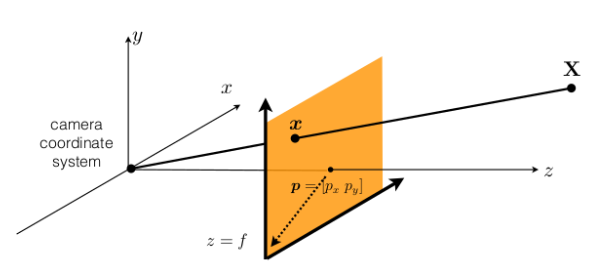
Step 2: Camera Space → Image Plane (z=1)
Project onto the normalized image plane (z = 1) via perspective division:
x_n = X_c / Z_c
y_n = Y_c / Z_c
This is ideal pinhole projection — no lens effects yet.
Step 3: Image Plane → Distorted Space

Apply lens distortion to the normalized coordinates. The distortion model differs by camera type.
Pinhole (Rectilinear) Distortion
For standard lenses, distortion has two components:
- Radial distortion: k₁, k₂, k₃ (barrel / pincushion effects)
- Tangential distortion: p₁, p₂ (lens–sensor misalignment)
r² = x_n² + y_n²

x_d = x_n(1 + k₁r² + k₂r⁴ + k₃r⁶) + 2p₁x_n·y_n + p₂(r² + 2x_n²)
y_d = y_n(1 + k₁r² + k₂r⁴ + k₃r⁶) + p₁(r² + 2y_n²) + 2p₂x_n·y_n
Fisheye Distortion
For wide-angle lenses, the model is angular (no tangential term):
- Radial distortion: k₁, k₂, k₃, k₄
r    = √(x_n² + y_n²)                            # distance from optical axis
θ    = atan(r)                                     # angle from optical axis
θ_d  = θ(1 + k₁θ² + k₂θ⁴ + k₃θ⁶ + k₄θ⁸)       # distorted angle
r_d  = tan(θ_d)                                   # distorted radius

x_d  = (r_d / r) · x_n
y_d  = (r_d / r) · y_n
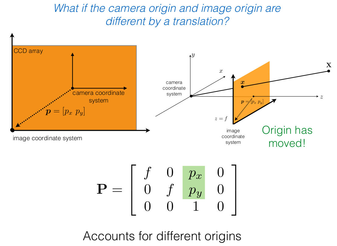
Step 4: Distorted Space → Pixel Space
Apply the intrinsic matrix K to convert to final pixel coordinates:
⎡ x ⎤       ⎡ f_x   s    c_x ⎤   ⎡ x_d ⎤
⎢ y ⎥   =   ⎢  0   f_y   c_y ⎥   ⎢ y_d ⎥
⎣ 1 ⎦       ⎣  0    0     1  ⎦   ⎣  1  ⎦
Where:
- f_x, f_y — focal lengths in pixels
- s — skew coefficient (typically 0)
- (c_x, c_y) — principal point (optical center in pixels)
Compact Forms
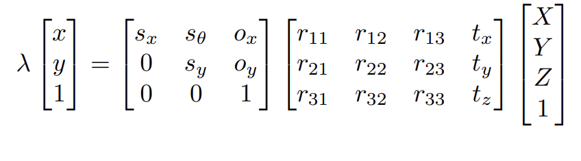
Ideal pinhole (no distortion):
    ⎡ x ⎤       ⎡ f_x   s    c_x ⎤   ⎡ r₁₁  r₁₂  r₁₃  t_x ⎤   ⎡ X ⎤
λ   ⎢ y ⎥   =   ⎢  0   f_y   c_y ⎥   ⎢ r₂₁  r₂₂  r₂₃  t_y ⎥   ⎢ Y ⎥
    ⎣ 1 ⎦       ⎣  0    0     1  ⎦   ⎣ r₃₁  r₃₂  r₃₃  t_z ⎦   ⎢ Z ⎥
                                                              ⎣ 1 ⎦
Real camera (with distortion):
p = K @ d( π( [R|t] @ X ) )
Where π is the perspective division (÷ Z_c) and d(·) is the lens distortion function.
Inverse Projection (2D → 3D)
The inverse pipeline is the exact mirror of forward. Because distortion is defined in normalized (post-K⁻¹) space, K⁻¹ must be applied before undistorting.

Pixel Space → [K⁻¹] → Distorted Space → [undistort] → Image Plane (z=1) → [ray or × Z_c] → Camera / World
  (x, y)                  (x_d, y_d)                      (x_n, y_n)
Step 1: Pixel Space → Distorted Space (K⁻¹)
Apply the inverse intrinsic matrix:
⎡ x_d ⎤         ⎡ x ⎤
⎢ y_d ⎥ = K⁻¹ @ ⎢ y ⎥
⎣  1  ⎦         ⎣ 1 ⎦
This is the direct inverse of Step 4 in the forward pipeline. The result is still distorted — we are now in the normalized plane but lens distortion has not been removed.
Step 2: Distorted Space → Image Plane (undistort)
The distortion equations are nonlinear and cannot be inverted analytically. Use iterative fixed-point methods.
OpenCV: cv2.undistortPoints(pts, K, dist_coeffs) (with P=None) applies K⁻¹ then undistorts, returning normalized coordinates.
Step 3a: Image Plane → Ray Direction (unknown depth)
At this point we have ideal normalized coordinates (x_n, y_n). Without knowing depth, we can only recover a ray:

The observed 3D point lies somewhere along this ray.
Step 3b: Image Plane → 3D Point (known depth Z_c)
If the depth Z_c in camera space is known:

Appendix:
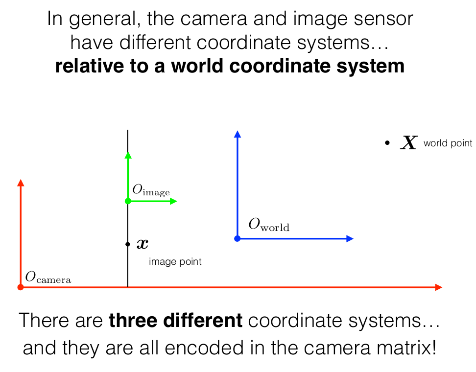
Coordinate Systems
The camera projection model involves three coordinate systems:
- World Coordinate Frame — the global 3D frame in which the scene lives.
- Camera Coordinate Frame — centered at the optical center of the lens, with the z-axis pointing along the optical axis.
- Image (Pixel) Coordinate Frame — the 2D plane onto which 3D points are projected, measured in pixels.
Intrinsics and Extrinsics
The full camera projection matrix P maps a 3D world point directly to a 2D pixel:
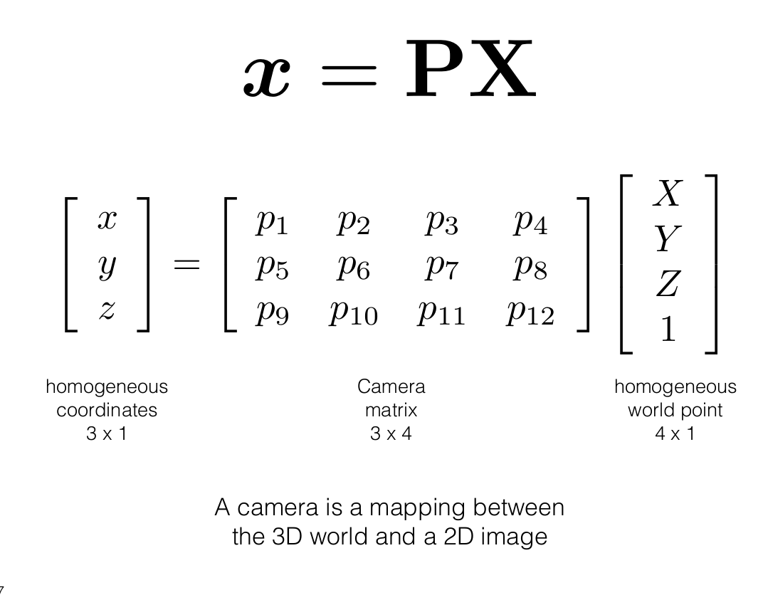
This 3×4 matrix decomposes into an intrinsic part (K) and an extrinsic part ([R | t]):
Undistort Pinhole
Given distorted normalized coordinates (x_d, y_d), recover undistorted (x_n, y_n):
x_n, y_n = x_d, y_d   # initial guess
tolerance = 1e-6

while True:
    x_n_prev, y_n_prev = x_n, y_n

    r² = x_n² + y_n²
    radial = 1 + k₁r² + k₂r⁴ + k₃r⁶
    x_n = (x_d - 2p₁x_n·y_n - p₂(r² + 2x_n²)) / radial
    y_n = (y_d - p₁(r² + 2y_n²) - 2p₂x_n·y_n) / radial

    if |x_n - x_n_prev| < tolerance and |y_n - y_n_prev| < tolerance:
        break
OpenCV: cv2.undistortPoints(pts, K, dist_coeffs) (with P=None) applies K⁻¹ then undistorts, returning normalized coordinates.
Undistort Fisheye
Given distorted normalized coordinates (x_d, y_d):
r_d  = √(x_d² + y_d²)
θ_d  = atan(r_d)
θ    = θ_d              # initial guess

while True:
    θ_prev = θ
    θ = θ_d / (1 + k₁θ² + k₂θ⁴ + k₃θ⁶ + k₄θ⁸)
    if |θ - θ_prev| < tolerance:
        break

r   = tan(θ)
x_n = (r / r_d) · x_d
y_n = (r / r_d) · y_d
OpenCV: cv2.fisheye.undistortPoints(pts, K, dist_coeffs) (with P=None).